In this tutorial, we will learn how to give analog output from Arduino. we will use a digital PWM pin to give analog output on a LED and which will result in led fade in and fade out.
Analog output is technically a digital PWM signal at high frequency.
How PWM signal works.
Always on, this output comes when simply set the digital PIN to HIGH mode.

Always OFF, when we set the digital pin to LOW.

50% Duty cycle.

25% Duty cycle.

PWM supported pin in Arduino UNO
NOTE: PIN numbers 3, 5, 6, 9, 10, 11 are only supported with PWM output.
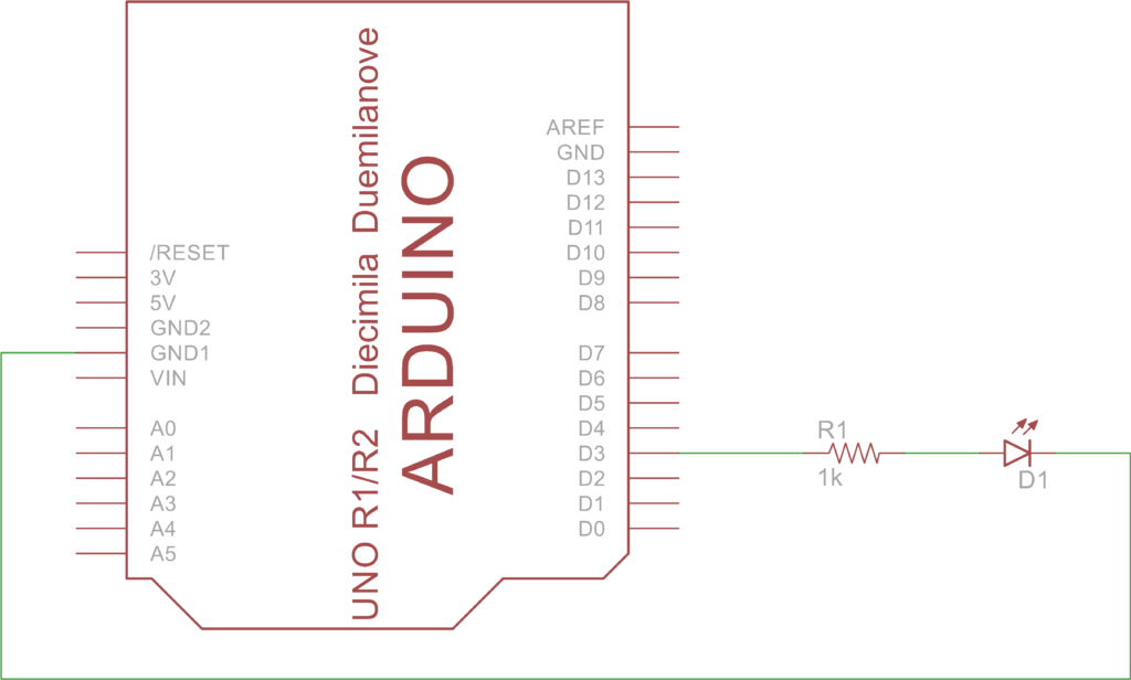
Circuit:

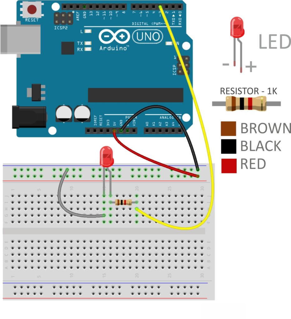
Breadboard connection:

Code:
/*
Tutorial for Analog Output.
Analog output is taken through PWM.
Prepared by Robo India.
www.roboindia.com
 */

int LED_ao = 3; // The LED attached to Pin 3 for analog output.

void setup()  {

  pinMode(LED_ao, OUTPUT); // Declaring Pin as output.
}


void loop()  {
 // Range of PWM is 0 to 255. So we are running FOR LOOP for 1 to 255.
  for (int brightness=1; brightness<=255; brightness++)  // For loop for Fade In effect.
    {
    analogWrite(LED_ao, brightness);  // LED will glow for value of 1 to 255.
    delay(20);                     // Small delay to see fade effect.
    }
  for (int brightness=255; brightness>0; brightness--) // Same FOR LOOP for Fade out effect.
    {
    analogWrite(LED_ao, brightness);
    delay(20);
    }
}
Syntax:
analogWrite(LED_ao, brightness);
analogWrite( PWM_pin_number, value );
PWM_pin_number – PWM pin number of Arduino.
value – brightness value from 0 to 255.
value defined the duty cycle of PWM output.
255 – Always on.
0 – Always off.
128 – 50% duty cycle.
Practice problem.
- Use 2 LEDs of different color and fade in fade out in different directions.
like if you are using red and yellow led than make red led fade in and yellow led fade out at the same time and vice versa.
